Production Capacity Sheet
- hidet77
- Nov 16, 2023
- 4 min read

One of the standardized work documents. Despite its importance, we don’t talk about this as often. This sheet is full of Toyota Production System thinking.
The name. By components or By process?
Machine cycle time
Tool change
Remark
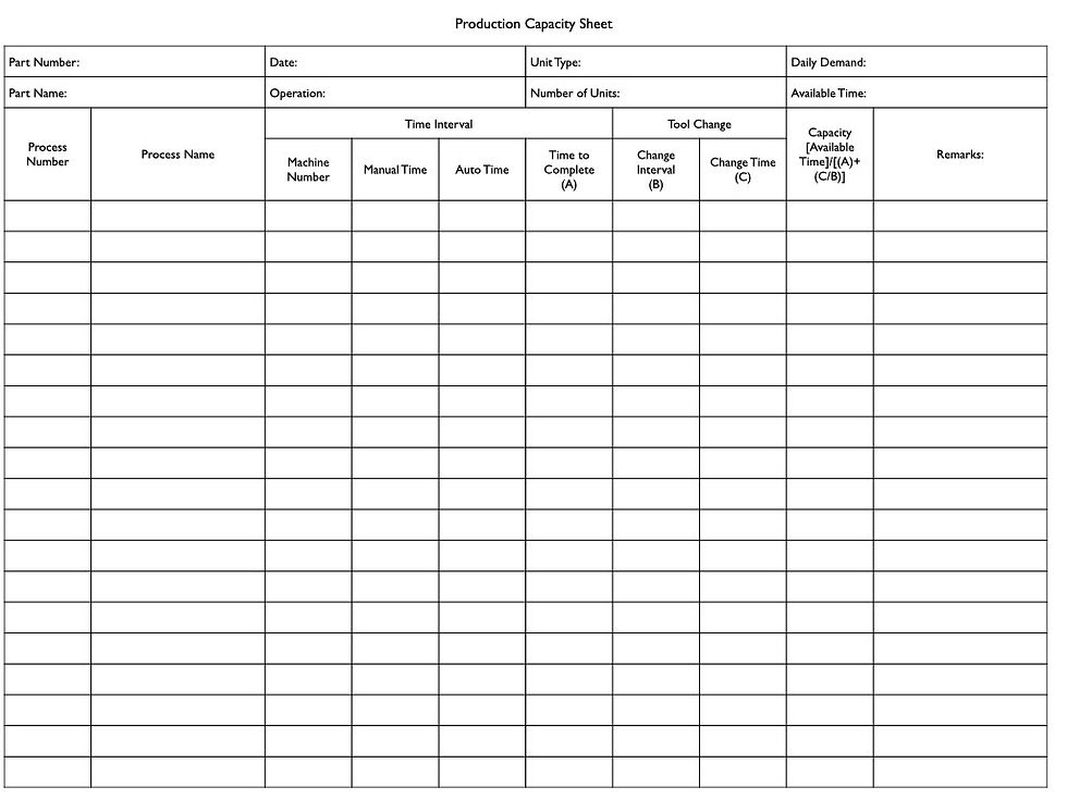
Production capacity sheet. This crucial sheet inside standardized work describes the machine's capacity. By paying attention to the details, we understand the essential aspects of the Toyota Production System.
The name. By components or by process?
The name in English is “Production capacity sheet.” But the name in Japanese contains a few more words. And I found several versions. One old name was “By component production capacity sheet.” 【部品別工程能力表】Another name is “By process production capacity sheet.” 【工程別工程能力表】
Names could be confusing. But understanding the difference in thinking will be necessary.

There is some history behind how this document evolved. I wrote about the vision Kiichiro Toyoda developed for their first plant in 1938. The third principle of this vision was to create a “By component process capacity sheet.” Yet, the operator’s standardized work was not a multiple process. It was a typical job-shop, one process, one operator condition. Taiichi Ohno introduced multiple machines and multiple processes by an operator in the late forties. From here, the nuance of “Process” has changed. “Process” meant multiple steps and machines. When I look at standardized work’s “Production capacity sheet,” it is organized by component and each process of that component. In other words, we collect in flow first, then the capacity of each process.

There are many similar formats in the world. And the same "By process production capacity" but not necessarily the same philosophy. The minor differences in the structure lead to flow or job shop. By process, by components format tries to maximize the use of an equipment. Yet, sacrifices flow. Collecting all information to create a flow by component is possible but complicated. You have a machine, but that might be the third process for one part and the fifth for another. Sometimes, they place the process sequence number, but there is no information about pre-prices and post-process. You need to dig into the data.
On the other hand, we must be careful because the “By component production capacity sheet” could lead to over-investment. This creates the perception that we need a dedicated set of machines to create a flow. Flow is essential, but expensive one is not. We need control over how expensive a flow can be. And this is where our creativity should kick in. One idea is to re-use old equipment.
We are talking about "By component, each process's capacity."
2. Machine cycle time
The section where we write down the machine cycle time is simple. Manual loading time + Automatic time. This represents a philosophy. Machine cycle time should not fluctuate.
I have been to many places where machine cycle time is not standardized. There are many technical reasons why it changes. Instead of jumping to such stories, start with defining one. In many cases, technical excuse comes first and no standard, leading to the machine's random settings or poor maintenance. I have been told once that each machine has “personalities.” The technical reason hides other variables, which leads to chaotic conditions.
The machine cycle time should be the best time without sacrificing the quality and machine life. An engineer should define this condition. If someone wants to change to improve, it should work with an engineer. And we must sustain it. Don’t think we lost performance, and it’s okay since we reported it [which is in many OEE thinking]. Such loss of productivity should not exist.
3. Tool change
The tool change section is also simple. This also has a similar story. Tool change work should be standardized, too.
Today, we have advanced machines with multiple toolings. We should follow the same philosophies of keeping things simple and standardized. One thing to consider is to design the connection of various tools to be standardized so that manual tool exchange work remains the same among different tools. There are careless designs of numerous tools with many connection types, like one using a hex cap and the other using a Philips screw. Why different? By keeping these simple, we eliminate the need to present multiple tools and search for the right one.
Another aspect to think about is the tool change frequencies. Can these be randomly set? It is more challenging to standardize at one frequency due to technical differences. Yet, keeping this frequency a random condition keeps the line under pressure on an unclear bomb that could explode in time. (That’s how an operator explained it to me.) In such cases, I try to develop multiple or divisor relationships with frequency. This way, there is some predictability on when the tool change will happen among multiple toolings or machines.
4. Remark
In the final remark section, we draw a simple line diagram that presents the relationships between manual and automatic work.
This section confirms the philosophy of separating human and machine works. This section will be a mess or impossible to draw if this is not accomplished. Another challenging case is the semi-automatic machines. Unfortunately, semi-automatic is not drawable in the form of a simple line. We should consider how to separate humans from this machine work.
“Production capacity sheet.” It’s not a sheet that we talk about it a lot. Yet, it is full of Toyota Production System philosophies. It is definitely not number-crunching paper. It is something we should create with cautious thinking. Often, it is very simple, but that is the condition that TPS tries to accomplish.


Comments